Things you need:
Soldering the board
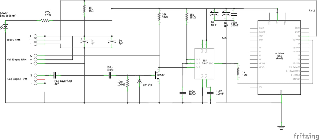
Soldering up the board is pretty straightforward, every component (and polarity where that applies) is clearly marked.
There's a few things to keep in mind:
Sensors
IMPORTANT: YOU MUST USE A RESISTOR SPARK PLUG AND/OR CAP TO AVOID INTERFERENCE ON THE SENSORS!
Software and connecting to pc
- Ardyno PCB
- Arduino UNO compatible board
- Components(see Partslist), cables, and sensors
- Arduino IDE software
- Simpledyno software
Soldering the board
Soldering up the board is pretty straightforward, every component (and polarity where that applies) is clearly marked.
There's a few things to keep in mind:
- Make sure the polarity line on the small signal diode matches up with the line on the PCB
- Make sure the flatspot on your LED lines up with the flatspot on the PCB
- Make sure the electrolytic capacitors are installed with negative where theres two small "-".
- Make sure the notch or dot on your 555 chip lines up with the notch on the PCB
Sensors
IMPORTANT: YOU MUST USE A RESISTOR SPARK PLUG AND/OR CAP TO AVOID INTERFERENCE ON THE SENSORS!
- For roller rpm you need a normally open npn hall sensor(or other npn digital sensor) that will accept 5v input voltage. I like the Honeywell 1GT101DC, it's rugged but a bit expensive, cheaper alternatives work just fine(ebay). Remember to use a shielded wire and connect sensor ground to the Ardyno board only, not to your dyno frame or bike(can cause ground loops).
- For engine rpm you can choose to either use a hall sensor(see above), or a capacitive clamp over the sparkplug wire. The cacitive clamp can be an actual small metal clamp, or just a wire twisted a few turns around the plug lead. Use shielded wire in both cases, with a hall sensor only ground to the board, with the capacitive clamp ground to both bike/engine and board. In some cases there's so much noise from the ignition system that using the capacitive clamp is impossible.
- The 6 analog inputs can be connected to some sensors directly, take a 0-5v signal from EGT-meters, AFR-meters etc. or drive sensors with the use of "breakout boards". A0 has a built in voltage divider and can accept either 0-5v or 0-15v
Software and connecting to pc
- Download and install Arduino IDE from arduino.cc
- Download the Simpledyno zip file from here and unpack it
- Connect your Arduino and upload the Simpledyno sketch file to it. Learn how to upload sketches to your board here
- Launch Simpledyno, follow the included instructions on how to connect your board to the software.